Tuesday, 13 March 2012

Transistors, Inputs and Outputs

As mentioned before transistors are used as transducer drivers.

Lets consider some systems.

An automatic street lamp will come on at night when the light level gets too low.
We can draw a systems diagram:


We know how to make a light sensor using a voltage divider with a LDR.
As the light level decreases the resistance of an LDR increases, and so the voltage dropped over it will increase.  This means that there will be a higher voltage signal in the dark if the LDR is at the bottom of the voltage divider.


Using a variable resistor as the top resistor will give you flexibility in the light level required to switch on the lamp.

The signal voltage produced by the light sensor will depend on the light level - this is the signal to the transducer driver (as in the system diagram) so next we have to add the transistor.


We can then lastly add the lamp.


This is how to take a system diagram to a circuit diagram.

Some output transducers need a bigger voltage or current than the transistor/sensing circuit can provide.  For this we need to use a relay - just as we did in the telescope project to make the motor turn because the Alphaboard circuit provided 5V and the motor required 12V.


This page in your notes (P39) shows the relay as a magnetic switch. This means that there is no physical connection between circuits with different power supplies, a magnet pulls a switch closed to complete a higher power circuit.

When a relay switches it creates a large ElectoMagnetic Force (EMF) which creates a very large current.  If this flows back into the transistor it will destroy it and your circuit wouldn't work. Therefore we have to add a diode over the relay to stop the back EMF destroying the transistor.


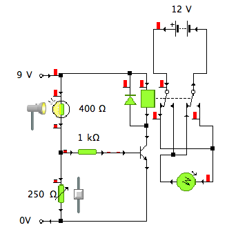
So our street lamp may require a bigger supply voltage than the sensing circuit.  So we can add a relay in to ensure the lamp lights brightly.


Note the diode.  It protects the transistor from back EMF as the relay switches.

Motors often need greater current/voltage to turn them, so we can use a relay:


This circuit uses a light sensor as its input made using a voltage divider with a LDR at the top and a variable resistor at the bottom.  So as the light level increases the resistance of the LDR will decrease, decreasing the voltage dropped over it, therefore increasing the voltage dropped over the variable resistor and the voltage out of the voltage divider.  When the voltage between the base and emitter (VBE) is 0.7v the transistor will saturate, allowing current to flow from the collector to the emitter, energizing the relay.  This will pull the switch closed in the motor circuit and the motor will turn.
Note that the motor circuit is connected using only one leg of the relay switch, so that when the relay is not energized nothing will happen.

However using the Single Pole double throw relay above only allows the motor to turn in one direction.  We can use a Double Pole Double Throw relay to allow the motor to turn in both directions: one when it is dark and one when it is light:


Combined Circuits

We have looked at series circuits and we have looked at parallel circuits, so now we must consider circuits which have elements of both.

You need to remember all the rules for each type of circuit:

In a series circuit the total of all the voltages dropped in the circuit must equal the supply.
In a parallel circuit the voltage dropped in each branch is the same.

In a series circuit the current is the same at all points.
In a parallel circuit the currents in each branch are added to give the total circuit current OR from Kirchoff's law, the current entering a node must equal the currents exiting a node.

In a series circuits all the resistances are added to give the total resistance.
In a parallel circuit the reciprocal  (1/Ω) are added, or if there are only two resistors in parallel the special total resistance formula can be used: Rt = Product/Sum.

Lets consider this circuit.


To work out where the series and parallel parts are follow your finger around the circuit.  When you reach a node (junction/join) you know that you have come to a parallel branch.

First you should work out the equivalent resistance of the parallel resistors.  This, put simply, is finding out what resistance value these two have created, or working out the single value of resistor which could replace these two.


This makes it easier to see that these two parts of the circuit are in series with each other, so we can then work out the total resistance:


Knowing the total resistance we can find the total circuit current:


So going back to the circuit as it was, we can see that the circuit current flows through R1, and it then splits.


So we can work out the voltage dropped over R1 and from that work out the voltage dropped over the parallel branches (remember that this will be the same voltage in each branch):


Knowing the voltage dropped over each of the parallel resistors and the resistance, we can work out the current using ohm's law.


And finally we can check if our current calculations are correct using Kirchoff's Law.

Power in Electrical Ciruits

Power is the rate at which an electrical circuit transfers electrical energy to another form - i.e. if we had a bulb it would be the rate at which electrical energy is transferred to heat and light energy.  It is dependent on the voltage and current flowing in the circuit.

Power is measured in watts.

Joule's law states that

P = IV 

where P = Power (W) I = Current (A) and V = Voltage (V)

We may not know current in our circuit, but instead we might know the resistance.  So we can combine this law, and Ohm's law to make different permutations of the same formula:

P = IV,  and V = IR  so P = I x I x R   so we can use the formula P = I2R

P = IV and I = V/R so P = V/R x V   so we can use the formula P = V2/R

Lets consider these circuits:


Voltage Dividers

Today we looked at how we can use two resistors in series to change a signal voltage.

We know from previous lessons that the voltage in a series circuit is shared between the components.  We can use a special type of series circuit to get a specific voltage.

For example if both resistors are of the same value then the voltage will be shared equally between them:

If one resistor is twice as big as the other, twice as much voltage will be dropped over it:


Remember that the whole supply voltage must be used in the circuit, there is none left over at the end!

We can work out the proportion of the voltage dropped over the bottom resistor using the equation:

              R2      
V2 = R1 + R2      x Vcc   (V2 might also be called Vo for Voltage Out of the voltage divider)
             20     
      = 10 + 20      x 12
         2
      = 3     x 12
      = 8v

In voltage dividers we are interested in the voltage dropped over the bottom resistor.  We can use this voltage as a signal to another part of the circuit.  However it is possible to use the equation to work out the voltage dropped over the top resistor by changing the equation so that instead of R2 on the top, it is R1

The application of voltage dividers is most useful when using input transducers like a thermistor, which changes resistance based on temperature, and a LDR, which changes resistance as the light level changes.  This change in resistance will result in a change of voltage.

Thermistors
First of all we will look at thermistors.  The resistance of a thermistor changes with temperature.  They are negative temperature coefficient (NTC) which means that the resistance will do the opposite of the temperature - i.e. as the temperature increases the resistance will decrease and as the temperature decreases the resistance will increase.

Consider these circuits:


The thermistor is the bottom resistor in a voltage divider.  As the temperature decreases, the resistance of the thermistor will increase.  Therefore the share of the supply voltage dropped over the thermistor will increase (remember the more resistance there is, the more voltage is required) and so the output voltage will increase.  This makes this circuit a cold sensor.

The thermistor is now at the top of the voltage divider.  The properties of the thermistor remain the same (temperature up > resistance down) but because it is now at the top of the voltage divider, the circuit will act as a heat sensor.  As the temperature increases the resistance of the thermistor decreases.  Therefore the share of the voltage dropped over the thermistor will decrease and so the share of the voltage dropped over the fixed resistor must increase and so the output voltage will increase as the temperature increases.

There are different types of thermistor with various temperature ranges.  They are all found on this graph:

This is a "log graph" as in reality the properties of the thermistor will form a curve and not a straight line which is very difficult to read.  So instead this type of graph is used and the axis need to be interpreted.  The temperature axis acts as you would expect and the only difference is the spacing.  The resistance axis, however, is more difficult and this is the bit people get stuck with.  Reading up from the bottom the units read > 10, 20, 30 etc then 100, 200, 300 etc, then 1000, 2000, 3000 etc. 

It is also important to note that the values nearer the top are closer together than those at the bottom.  So a half way point is not half way between the two values, but closer to 1/3 of the value.  i.e. between 1k and 2k, half way would be 1.3k.

To find a value, read along the axis of the value you know (you could be given either the temperature and asked to find the resistance, or the resistance and be asked to find the temperature)  This graph shows that at 25°c the resistance of a type 4 resistor is 50kΩ.
 LDR - Light Dependent Resistor
The light dependent resistor will change resistance as the light level changes.  As the light level increases, the resistance decreases and as the light level decreases, the resistance increases.  LDRs can be used in the same way as thermistors in a voltage divider circuit.

Consider these circuits:

This is a dark sensor - as the light level decreases the resistance of the LDR increases and therefore the voltage dropped over the LDR increases and the voltage out of the voltage divider increases.

This is a light sensor - as the light level increases the resistance of the LDR decreases and therefore the voltage dropped over the LDR decreases so the voltage over the fixed resistor increases and the voltage out of the voltage divider increases.

Just like thermistors there is a graph to show the change of resistance with the change in light level.  This is another log graph so you need to be aware of the axis.  We only need to look at one type of LDR, the ORP12.  You need to be aware that in this graph, the resistance is measured in KΩ.


This graph shows how to read the graph - at a light level of 200 lux the resistance is 600Ω.

It may be necessary to adjust the sensitivity of the circuit, i.e. change the "trigger" temperature or light level.  In this example a signal voltage of 5v is required.  First of all we can use the variable resistor to achieve this voltage at a temperature of 0°c.

We can adjust the temperature which produces that 5v signal voltage to 20°c by changing the resistance of the variable resistor.

Series and Parallel Circuits

Parallel circuits have more than one path for the current to flow along, they are set up in "branches".  Each branch receives the supply voltage and the current is shared.  In a series circuit if one component fails then the circuit is broken and current can't flow.  In a parallel circuit if one component fails the others can still operate as they are in a different branch.


Resistors can only come in certain values and so it may be necessary to connect them in series or parallel to create a different total resistance.

Resistors in parallel use the equation:
                1
Rt = R1 + R2 + R3 . . .  (this is absolutely not the same as Rt = R1 + R2 + R3!)

This is known as the reciprocal.  You don't need to understand the maths, but it helps if you do.  The reciprocal is the inverse of a number.  You may find this website useful.


Consider this circuit:

We need to find the total or equivalent resistance of the pair of resistors.

Because there are only two resistors it is possible to use the special equation: 


WARNING!  If you plug these numbers straight into your calculator, it will follow BODMAS and so do everything else and then add R2 at the end.  Therefore you must either do the two sums separately and then divide, or use the brackets function on your calculator.


 Current in a parallel circuit is shared between the branches.  Kirchoff's current law states:

The current entering a node (join) equals the current exiting a node.  We use this to show that when the current splits at the node the total current = the sum of the currents in all the branches of a parallel circuit.


So we can find out both the total circuit current and the current in each of the branches:

      
IT = RT
         12
     = 825
     = 14.5mA

        V                                  V
I1 = R1                                      I2 = R2
         12                                 12
     = 1100                         = 3300
     = 10.9mA                    = 3.63mA


Check:  IT = I1 + I2
                  = 10.9 x 10⁻³ + 3.63 x 10-3
                       = 14.5mA                               So our calculations are correct!


Ohms Law

We looked at calculations for series circuits using both Kirchoff and Ohm's Laws.

Consider the circuit below.


First we can find the total circuit resistance. Because the resistors are end to end in a series circuit, to find the total resistance is the sum of all the resistances:

Rt = R1 + R2 + R3
    = 2300 + 7500 + 500
    = 10300 Ω
    = 10.3 KΩ

Now that we know both the total resistance of the circuit and the supply voltage we can work out the current flowing in the circuit using ohm's law.

      V
I = R
      24
   = 10300
   = 2.3mA

Because this is a series circuit the current will be the same through each resistor, so now we know the resistance and current of each resistor we can use ohm's law to calculate the voltage dropped over each resistor.

V1 = IR1
     = 2.3 x 10-3 x 2300
     = 5.29v

V2 = IR2
     = 2.3 x 10-3 x 7500
     = 17.25v

V3 = IR3
      = 2.3 x 10-3 x 500
      = 1.5v

We can then check our answer using Kirchoff's Voltage law (all voltages dropped in a circuit must equal the supply)

Vt = V1 + V2 + V3
    = 5.29 + 17.25 + 1.5
    = 24v                                  So our calculations are correct! :)

You can use a variants of this method to find out missing information from circuits.  You may find it useful to write down all the information that you do know at the side of your paper so that it is more obvious where the gaps are and therefore which calculations you need to do.

Tuesday, 10 January 2012

Pneumatics Revision

Today we looked at this circuit and answered the questions below.   I will leave the answers as a comment so that you can attempt the questions again first before reading:


You may also find this website useful.

Wednesday, 14 December 2011

Term 1 Evalution

I'd like you to take a moment to reflect on the work you have done so far in Technological Studies this term.

Can you leave a comment below answering these questions:

  • What topic you enjoyed the most and why, 
  • What you found difficult or that you least enjoyed and why. 
  • How you have enjoyed working- i.e. individually, in pairs, practically, theoretically, using theory to answer written questions, challenges and problem solving
  • How do you prefer to be assessed - i.e. reports, tests per topic, end of term tests, practically through challenges
  • What resources have you used this term - i.e. printed notes on topics, Can Do Statements, own notes made in class or using can do statements, the blog, external sources like google searching

Wednesday, 16 November 2011

Telescope Project

By this stage we should have completed the pre-building sections outlined here:

Situation: A quick statement giving the background for this project (copy from notes)

Problem: A quick statement giving the problem to be solved (copy from notes)

Analysis: A break down of the problem to identify the parts of the system which will have to be designed. This should take the form of an analysis statement describe what you will need to do to solve this problem (without coming up with a solution!), a system diagram and a description of how each of the subsystems/blocks work together.

Performance Criteria: A numbered list of statements of what your system should do in order to solve the problem effectively.  Copy the first three and then add your own.  For this project break this down into Electrical Control Performance Criteria, Mechanical System Performance Criteria and Overall Performance Criteria.

Ideas: This is the most extensive section. For each of the blocks in your system diagram you need to come up with as many ideas as possible.  Namely the motor control system and the mechanical system.  Here I would expect to see 4 or 5 ideas for the motor control and 4 or 5 ideas for the mechanical system showing a clear development in your ideas.  Each idea should have comments which reference back to the Performance Criteria - "+" points and "-" points which show the suitability for each idea.  Mechanical ideas should include a schematic diagram and Velocity Ratio calculations.  Electronic control ideas could be tested using croc clips and printed off. They should include truth tables as well as the circuit diagrams clearly showing the inputs and outputs you require and which logic gates you need.

Build/Test:  In this section you should answer the questions:
  • How did you build your system?
  • What equipment did you use (building and testing)?
  • How did you test your system?
  • What were your results?
  • How did this compare to the calculated speed?
You also need to include a schematic diagram of your final mechanical solution, a circuit diagram of your final motor control system (and/or Croc clips simulation), a photo (or two) and all of your calculations clearly showing the Velocity Ratio and the speeds. You will find a croc clips simulation of the transducer driver and relay on the server.  You can add this to the end of your logic simulation for the whole circuit.

Evaluation:  In this section you must evaluate the success of your project/system. 
  • Look back at the performance criteria and answer each one in turn, was it successful?  How do you know?  If not why not and what could you do to improve it?  
  • Why do you think that your system didn't turn at your calculated speed?  How did you over come this, or what could you do in the future?
  • Are there any improvements you could make to your solution as a whole? 
(There must be something you can do to improve, I don't like to see reports which say my system was perfect, or that it fulfilled all the PC.  The more you are honest and write about how it worked or didn't the better a report it will be!)

Wednesday, 26 October 2011

Digital Electronics - Logic

Digital electronics looks at a signal which is either high (1) or low (0) and nothing in between as shown in these two graphs.


The logic gates you need to know about and their truth tables are shown below.  Remember that inputs are labelled from the beginning of the alphabet (A) and outputs from the end (Z).

You have to be able to use these logic gates in complex systems which may require more than one gate.

i.e. Draw the circuit and truth table for a circuit which will switch on a car warning light if it gets too cold, or if the wheel sensor senses a skid as long as the ignition is switched on.


It is important to note that the extra columns D and E are midpoints in the circuit and including them in our truth table can help us work out when the output will switch on.  These are not to be confused with the three inputs labelled A, B and C and so do not effect the number of possible combinations.

Boolean Algebra is another way of describing a logic truth table or circuit.  Just like any other Algebra you need to know the operators to be able to write the equations.

They are:


You need to be able to go between an English statement, a truth table, a logic circuit and a Boolean expression.

When considering digital electronics you need to know about logic gates and the functions they perform.  All digital signals are either on or off, nothing in between.

From a Boolean expression you can work out which logic gates you will need to perform each part:


To derive a Boolean expression from a truth table you must identify when the output is on, writing an expression for these lines and then combining each of these expressions with an OR operator.


You can also derive a Boolean expression from a circuit diagram by following the signal using the original inputs and the Boolean operators: