Wednesday 14 December 2011

Term 1 Evalution

I'd like you to take a moment to reflect on the work you have done so far in Technological Studies this term.

Can you leave a comment below answering these questions:

  • What topic you enjoyed the most and why, 
  • What you found difficult or that you least enjoyed and why. 
  • How you have enjoyed working- i.e. individually, in pairs, practically, theoretically, using theory to answer written questions, challenges and problem solving
  • How do you prefer to be assessed - i.e. reports, tests per topic, end of term tests, practically through challenges
  • What resources have you used this term - i.e. printed notes on topics, Can Do Statements, own notes made in class or using can do statements, the blog, external sources like google searching

Wednesday 16 November 2011

Telescope Project

By this stage we should have completed the pre-building sections outlined here:

Situation: A quick statement giving the background for this project (copy from notes)

Problem: A quick statement giving the problem to be solved (copy from notes)

Analysis: A break down of the problem to identify the parts of the system which will have to be designed. This should take the form of an analysis statement describe what you will need to do to solve this problem (without coming up with a solution!), a system diagram and a description of how each of the subsystems/blocks work together.

Performance Criteria: A numbered list of statements of what your system should do in order to solve the problem effectively.  Copy the first three and then add your own.  For this project break this down into Electrical Control Performance Criteria, Mechanical System Performance Criteria and Overall Performance Criteria.

Ideas: This is the most extensive section. For each of the blocks in your system diagram you need to come up with as many ideas as possible.  Namely the motor control system and the mechanical system.  Here I would expect to see 4 or 5 ideas for the motor control and 4 or 5 ideas for the mechanical system showing a clear development in your ideas.  Each idea should have comments which reference back to the Performance Criteria - "+" points and "-" points which show the suitability for each idea.  Mechanical ideas should include a schematic diagram and Velocity Ratio calculations.  Electronic control ideas could be tested using croc clips and printed off. They should include truth tables as well as the circuit diagrams clearly showing the inputs and outputs you require and which logic gates you need.

Build/Test:  In this section you should answer the questions:
  • How did you build your system?
  • What equipment did you use (building and testing)?
  • How did you test your system?
  • What were your results?
  • How did this compare to the calculated speed?
You also need to include a schematic diagram of your final mechanical solution, a circuit diagram of your final motor control system (and/or Croc clips simulation), a photo (or two) and all of your calculations clearly showing the Velocity Ratio and the speeds. You will find a croc clips simulation of the transducer driver and relay on the server.  You can add this to the end of your logic simulation for the whole circuit.

Evaluation:  In this section you must evaluate the success of your project/system. 
  • Look back at the performance criteria and answer each one in turn, was it successful?  How do you know?  If not why not and what could you do to improve it?  
  • Why do you think that your system didn't turn at your calculated speed?  How did you over come this, or what could you do in the future?
  • Are there any improvements you could make to your solution as a whole? 
(There must be something you can do to improve, I don't like to see reports which say my system was perfect, or that it fulfilled all the PC.  The more you are honest and write about how it worked or didn't the better a report it will be!)

Wednesday 26 October 2011

Digital Electronics - Logic

Digital electronics looks at a signal which is either high (1) or low (0) and nothing in between as shown in these two graphs.


The logic gates you need to know about and their truth tables are shown below.  Remember that inputs are labelled from the beginning of the alphabet (A) and outputs from the end (Z).

You have to be able to use these logic gates in complex systems which may require more than one gate.

i.e. Draw the circuit and truth table for a circuit which will switch on a car warning light if it gets too cold, or if the wheel sensor senses a skid as long as the ignition is switched on.


It is important to note that the extra columns D and E are midpoints in the circuit and including them in our truth table can help us work out when the output will switch on.  These are not to be confused with the three inputs labelled A, B and C and so do not effect the number of possible combinations.

Boolean Algebra is another way of describing a logic truth table or circuit.  Just like any other Algebra you need to know the operators to be able to write the equations.

They are:


You need to be able to go between an English statement, a truth table, a logic circuit and a Boolean expression.

When considering digital electronics you need to know about logic gates and the functions they perform.  All digital signals are either on or off, nothing in between.

From a Boolean expression you can work out which logic gates you will need to perform each part:


To derive a Boolean expression from a truth table you must identify when the output is on, writing an expression for these lines and then combining each of these expressions with an OR operator.


You can also derive a Boolean expression from a circuit diagram by following the signal using the original inputs and the Boolean operators:

Monday 26 September 2011

Your Motor Speed Project

So you have designed and built a mechanical system which had a slow enough output speed so that you could count it and and use the known velocity ratio to work out the motor speed.  This is a quick guide to help you write up the report which is due in on:

Monday 3rd October

First of all the "pre-building" section:

Situation: A quick statement giving the background for this project (copy from notes)

Problem: A quick statement giving the problem to be solved (copy from notes)

Analysis: A break down of the problem to identify the parts of the system which will have to be designed. This should take the form of an analysis statement (copy from notes), a system diagram (copy from notes) and a description of how each of the subsystems/blocks work together.

Performance Criteria: A numbered list of statements of what your system should do in order to solve the problem effectively.  Copy the first three and then add your own.

Ideas: This is the most extensive section. For each of the blocks in your system diagram you need to come up with as many ideas as possible.  Namely the motor control system and the mechanical system.  Here I would expect to see at least two ideas for the motor control and 4 or 5 ideas for the mechanical system showing a clear development in your ideas.  Each idea should have comments which reference back to the Performance Criteria - "+" points and "-" points which show the suitability for each idea.  Mechanical ideas should include a schematic diagram and Velocity Ratio calculations.

Build/Test:  In this section you should answer the questions:
  • How did you build your system?
  • What equipment did you use (building and testing)?
  • How did you test your system?
  • What were your results?
  • How did this compare to the nominal speed of 3000 rev/min?
You also need to include a schematic diagram of your final mechanical solution, a circuit diagram of your final motor control system, a photo (or two) and all of your calculations clearly showing the Velocity Ratio and the speeds.

Motor Control Circuit


Evaluation: Here you need to refer back to each of your performance criteria.  In turn discuss how successful your system was at fulfilling the performance criteria statement.  If it was not a success, why not?  And what could you do to improve this in the future?  If it was a success, how did you know?  After you have looked at each statement you should write a short conclusion taking into account all of your findings and your overall system success.

Friday 16 September 2011

Today's Mechanisms Mini Test

1. Which is the stroke of the cam? a,b,c or d?


2. a) Name this mechanism: Worm and wheel


b) Label part A: worm
c) Label part B: wheel

3. Other than the mechanism above, name a mechanism which allows rotation in one direction only, and draw the schematic diagram of it.

              Ratchet and Pawl

4. a) Calculate the Velocity Ratio of this mechanical system.


       VR = B/A x D/C
             = 10/1 x 24/12
             = 10 x 2
             = 20


b) Calculate the output speed if A is turning at 60 rev/s
           VR = input motion/output motion
           20  = 60/output
      output = 60/20
                 = 3 rev/s

5. Draw and label two mechanisms which are rotary to reciprocating motion.
 Crank and slider
 Cam and Follower


6. State how to calculate the Velocity Ratio of a pulley.

Count the number of ropes (not including the effort rope)

or use the equation VR = distance moved by input/distance moved by output.

Mechanisms

Types of motion
  • Linear - movement in a straight line - i.e. a train
  • Rotational - movement in a circle - i.e. the wheels of the train
  • Reciprocating - back and forth movement in a straight line - i.e. a pneumatic drill
  • Oscillating - back and forth movement along an arc - i.e. a pendulum
Levers
Levers use distance to magnify force. The further away from the pivot the force is applied, the more it is magnified, therefore levers can be used to lift heavy loads with smaller forces.

So, in this example, the force we are trying to lift is 30N, it is magnified by 5 (5cm away from the pivot) the input force we need to put in is magnified by 15cm, therefore we have to apply an input force of 10N.

Pulleys

Pulleys are another mechanism used to magnify a force by a distance to make something easier to lift.  By increasing the distance of rope pulled through the mechanism less force can be used.  This only works with more than one pulley.

The mechanical advantage is a way of describing how much easier the load is to move with the pulley.  You can work out the mechanical advantage by using the equation:
                        load
             MA = Effort

The velocity ratio concerns the distances covered by both the load and the effort.  You can work out the velocity ratio by using the equation:
                       distance moved by load
            VR = distance moved by effort
You could also count the ropes (not including effort) to find the velocity ratio.

No mechanical system is 100% efficient due to friction in the moving parts, so you will need to put in more force in real life than in calculation to move the load.  The efficiency can be calculated using the equation:
                               Mechanical Advantage
          Efficiency =       Velocity Ratio

Rotary Mechanisms

All rotary mechanisms are used to increase or decrease speed, and/or change the rotation through different angels (most commonly 90)

You need to know about:
  • Spur Gears (Gear trains plus using an idler)
  • Chain and Sprocket
  • Belt and Pully
  • Worm and Wheel
  • Face Gears
  • Bevel Edge Gears

The velocity ratio of all rotary systems can be found using the generic equation:
                       the amount of input motion
            VR = the amount of output motion

However we can use simpler equations when we know the size/number of teeth on a gear.  This can apply to chain and sprocket, meashed gears, bevel edged gears and face gears.  If you want to find the Velocity Ratio of a belt and pulley, you can follow the same theory but you will have to use the diameter of the pulley as it will have no teeth.

A smaller gear will always turn faster, therefore is a small gear is driving a bigger gear you will get a speed reduction so you are looking for the Velocity Ratio to be a fraction.

So if gear A is the driver, and gear B is the driven, you can find the VR = A/B = 12/18 or simplified to 2/3.  So if gear A turned at 300 rev/min, gear B would turn at 2/3 of that speed = 200 rev/min.


If a larger gear is driving a smaller gear you will have an increase in speed and are therefore looking for a whole number as your velocity ratio.  So if gear B was the driver and gear A the driven the VR = B/A = 18/12 = 1.5.  So if gear B turned at 300 rev/min, gear A would turn at 1.5 x 300 = 450 rev/min.

When deciding between a chain and sprocket and a toothed belt you need to consider the function of the mechanism.  A chain and sprocket is very good for eliminating slip, but if something jams in the mechanism and a motor is being used as your input, the motor will be trying to turn but can't so will burn out, a belt would allow the motor to still turn as it would slip over the pulleys and so the motor is protected.  Something with manual input like a bike is very suited to a chain drive to ensure that every rotation of the pedals results in a turn of the wheel.

You can try to increase friction between the belt and the pulley by changing the type of belt to a V-belt or a toothed belt.

To make sure that the belt does not stretch so that it falls off the pulley, a tensioner or jockey wheel may have to be used.


Worm and Wheel
A worm and wheel is a special rotary system as it only allows rotation in one direction - i.e. the worm can only ever be the driver so acts as a brake.  The worm and wheel also produces a big reduction in speed as the worm only has one tooth.  So VR = 1/number of teeth on worm.


Bevel Edge Gears
Bevel edge gears often do not have a difference in size as their main purpose is to transmit the rotation through 90.


Face Gears
Face gears transmit rotation through 90 and can also have a velocity ratio by changing the size of the gears used.


Compound Gear Systems
Compound gear systems combine mechanisms to produce a greater velocity ratio.  This is done by adding two gears on the same axle.  As these must be turning at the same speed, there is no velocity ratio between them, but now the driver of the second "pair" is turning at the same speed as the driven of the first "pair."


The above picture and graph shows a motor turning at 120 rev/min.  There is a great reduction in speed with the worm and wheel - VR = 1/10 (the blue line shows the speed of the wheel) a further reduction with the first chain drive - VR = 10/20 (the green line) and a last reduction with the second chain drive - VR = 15/25 (the purple line).

So we can work out the total VR:

VR = 1/10 x 10/20 x 15/25
      = 0.03

The output speed will be the motor speed x VR so:

Output speed = 120 x 0.03
                      = 3.6 rev/min

If an idler mechanism was used, the effect of the speed reduction would be greatly reduced as the idler does not affect the velocity ratio, only the driven and the driver.

Rotary to Linear

The rack and pinion turns the rotary motion of the pinion into the linear motion of the rack.  You can do calculations based on the number of teeth per metre on the rack and the speed of the rack.


i.e. if the rack has 100 teeth per metre and the pinion has 10 teeth, it has to turn at 10 revolutions a second for the rack to move 1m/s.

Rotary to Reciprocating


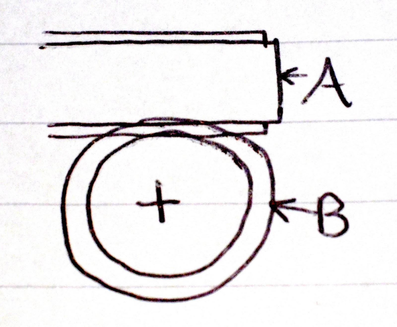
Crank and Slider: A crank is motion off centre of a circle.  This could be a single member, or a wheel.  The off centre motion pushes the slider back and forth, thus creating reciprocating motion.


Cam and Follower: The raised section of a Cam pushes a follower up and the dewll makes it fall again.  There are many shapes of Cam, the most common of these being a pear shaped cam.

Click here for more information about cam and follower

Safety Mechanisms
Sometimes it is necessary to ensure rotation in one direction only.  As mentioned before, a worm and wheel could be used for this purpose.  Alternatively a Ratchet and Pawl could be used.  This works by shaping the teeth on the ratchet so that in one direction the pawl slides over them and in the other direction gets stuck, stopping the mechnism.