Digital electronics looks at a signal which is either high (1) or low (0) and nothing in between as shown in these two graphs.


i.e. Draw the circuit and truth table for a circuit which will switch on a car warning light if it gets too cold, or if the wheel sensor senses a skid as long as the ignition is switched on.

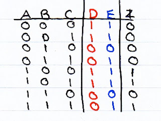
It is important to note that the extra columns D and E are midpoints in the circuit and including them in our truth table can help us work out when the output will switch on. These are not to be confused with the three inputs labelled A, B and C and so do not effect the number of possible combinations.
Boolean Algebra is another way of describing a logic truth table or circuit. Just like any other Algebra you need to know the operators to be able to write the equations.
They are:

You need to be able to go between an English statement, a truth table, a logic circuit and a Boolean expression.
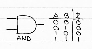
When considering digital electronics you need to know about logic gates and the functions they perform. All digital signals are either on or off, nothing in between.
From a Boolean expression you can work out which logic gates you will need to perform each part:
From a Boolean expression you can work out which logic gates you will need to perform each part:

To derive a Boolean expression from a truth table you must identify when the output is on, writing an expression for these lines and then combining each of these expressions with an OR operator.

