The first flowchart is to practice asking about the condition of an input:
First you must choose which pins you are going to use as outputs and which as inputs. Looking at the board you know that pin 7 is a red LED and 5 is a green LED. I'm going to use pin 0 as my switch.
So I need to tell the microprocessor this:
init: let dirs = %10100000 'Sets pin 7 and 5 as outputs
symbol green = 5
symbol red = 7 Now I can write my main program. If I want to use English words, I must first of all tell the microprocessor this as well by setting the English words as symbols. If you prefer not to do this, use the black commands, if you would like to do this, follow the purple programming language.
To ask a question I need to use an IF . . . THEN . . . statement in relation to my input pin. Then I need to tell the microprocessor which bit of program to go to when my input is on, and when it is not. If the statement is not true, it will not go to the label which follows THEN but to the next line instead.
main: if pin0 = 1 then green_on 'Check the input pin, if it is on, go to the
'green_on sub-procedure.
goto red_on 'If the input pin is off, go to the
'red_on sub-procedure
red_on: high 7 high red 'Switch on the red LED
low 5 low green 'Switch off the green LED
goto main 'Loop back to the start to test the input
green_on: high 5 high green 'Switch the green LED on
low 7 low red 'Switch the red LED off
goto main 'Loop back to the start to test the input
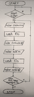
The second flowchart incorporates testing an input and using a counter loop. To repeat something a certain number of times, you must use a temporary memory file in the RAM to store the number of times the loop has been repeated. Often we will use b0 for this purpose. Again, if you want to call b0 something in English you must use the symbol command.
The PBASIC language required to repeat a sequence is a FOR . . . NEXT loop. For must go at the top of the sequence and next at the bottom. Anything you write in between FOR and NEXT will be repeated.
Motors, as described earlier in the blog, must be connected using the push-pull driver on the output driver. 7&6 control one motor, and 4&5 control another motor if you require it. It is important to use the correct pairing to ensure that your motor will turn.
The program for this flowchart would therefore be:
init: let dirs = %11000000 'sets 7 and 6 as outputs
symbol counter = b0
main: if pin0 = 0 then main OR main: if pin0 = 1 then motor 'both of these statements check
goto main the input.
motor: for counter = 1 to 5 'Starts the loop to repeat 5 times
high 7 'motor clockwise on
pause 10000 'wait 10 seconds
low 7 'motor clockwise off
high 6 'motor anticlockwise on
pause 10000 'wait 10 seconds
low 6 'motor anticlockwise off
next counter 'If it has not been repeated 5 times, loop back to motor
end
The third flowchart is in two parts. This shows that the sequence uses a sub-procedure. Where "alarm" is in the main flowchart, it means that the whole of the alarm flowchart fits into that box. So from the main flowchart, the sequence goes to the start of alarm, and at the end of alarm it returns to the main program and follows the arrow back round to the start.
Here is the program:
init: let dirs = %10000000 'sets pin 7 as the output (buzzer)
main: if pin0 = 0 then alarm 'if the door is opened go to the sub-procedure alarm
if pin1 = 0 then alarm 'if the window is opened go to the sub-procedure alarm
if pin2 = 0 then alarm 'if the door mat is stepped on go to the sub-procedure alarm
goto main 'go back to the start and test the inputs again.
alarm: high 7 'buzzer on
pause 500 'wait half a second
low 7 'buzzer off
pause 500 'wait half a second
if pin3 = 0 then alarm 'test the reset switch, if it is not pressed then continue sounding the alarm
return / goto main 'return to the main program.


No comments:
Post a Comment